How to Build a PC
There are numerous pre-built gaming PCs available in the market; however, the satisfaction derived from using a self-assembled one is unparalleled. Although the process of constructing a computer is not overly challenging, it can be quite intimidating for individuals attempting it for the first time. In support of those embarking on their initial build, or perhaps their first one in several years, a comprehensive step-by-step guide to PC assembly has been compiled.
Before commencing, it is important to note that this guide exclusively focuses on the assembly aspect. This means that selecting the necessary components is a prerequisite. To aid in this selection process, a list of tested and approved cases, CPUs, GPUs, motherboards, SSDs, power supplies, and RAM modules is available. Alternatively, if one seeks to build a system within a specific budget, they can refer to the “Best PC Builds” page for assistance.
Another crucial consideration is the uniqueness of each build. The sequence presented here is influenced both by personal preference and the specific requirements of the intended build. For instance, if an individual possesses a sizable aftermarket cooler that extends over the RAM slots, it may be necessary to install the memory modules first. Similarly, when installing an AIO cooler radiator at the top of the case, it is often advisable to connect power and fan cables in that area before the cooler obstructs access to the ports and headers.
Likewise, in cases where the computer chassis is particularly compact or constricted, or if a large high-end graphics card is being used, the order of installation may need to be adjusted. This is due to the fact that the graphics card can obstruct access to numerous ports, slots, and connectors.
In summary, it should not come as a surprise if some backtracking is required, and certain components need to be removed and reinstalled to accommodate the unique characteristics of an individual’s build. Frustration should be avoided, as such challenges are commonplace, even for individuals who have been building PCs regularly for many years.
Be Prepared
Before commencing the PC assembly process, one should prepare their workspace adequately. It is essential to ensure that all necessary components and tools are readily available. The following items, at a minimum, should be on hand:
- Phillips head screwdrivers (either #1 or #2 should suffice)
- The motherboard manual
- Zip ties and/or twist ties for efficient cable management
- A flashlight (to assist in locating dropped screws)
- Thermal paste (though many coolers now come with pre-applied paste)
- a container or magnetic tray to keep screws organized
- Installation media for the chosen operating system
- Band-aids (as a precautionary measure)
Some PC builders endorse the use of anti-static mats or wrist straps. However, unless one resides in an exceptionally dry environment, is building on a surface that is entirely metal or all-plastic, or engages in static-inducing activities such as rubbing socks on carpet while building, the risk of shorting out the PC or its components is relatively low. Nevertheless, prioritizing safety is always commendable. Therefore, if concerns regarding static electricity persist, it is advisable to take appropriate precautions and utilize an anti-static strap for added security.
Connect Components to the Motherboard
Some individuals opt to install the motherboard within the case as their initial step. However, in most cases, it is typically more convenient for builders to connect essential components such as the CPU, M.2 storage, and RAM without having to lean over the edge of the case.
The CPU
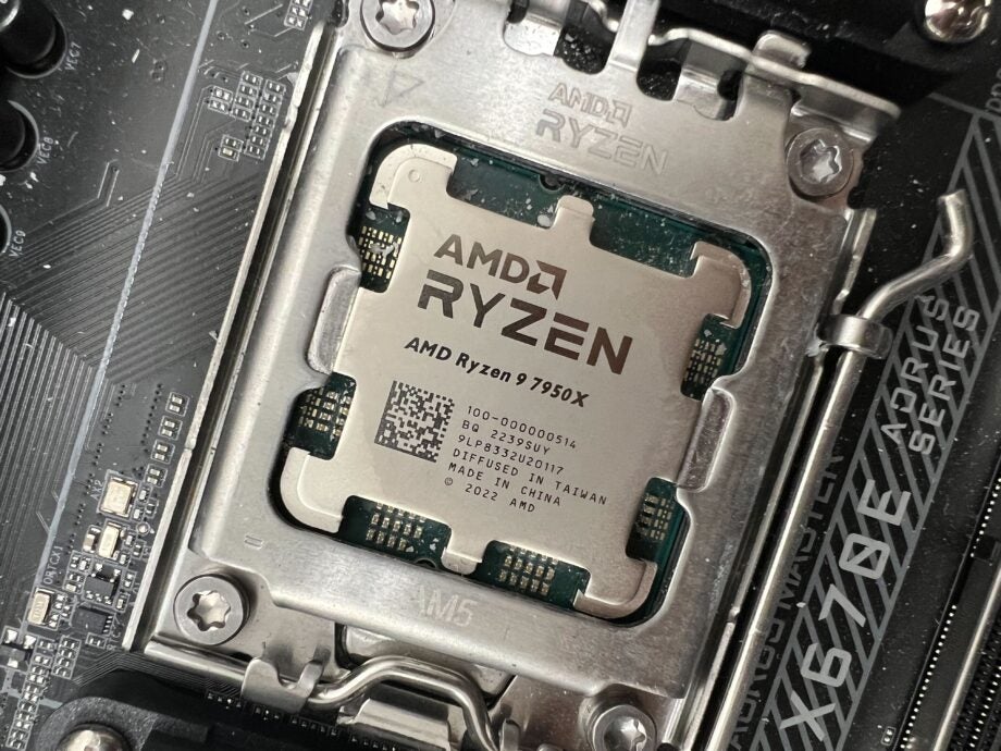
Regardless of whether one opts for an Intel or AMD-based build, the initial procedure entails the removal of the plastic cover safeguarding the socket. Afterward, the tension lever on the CPU should be released, and in the case of the latest AMD and Intel platforms, the metal retaining bracket should be lifted, allowing for the insertion of the processor into the CPU socket.
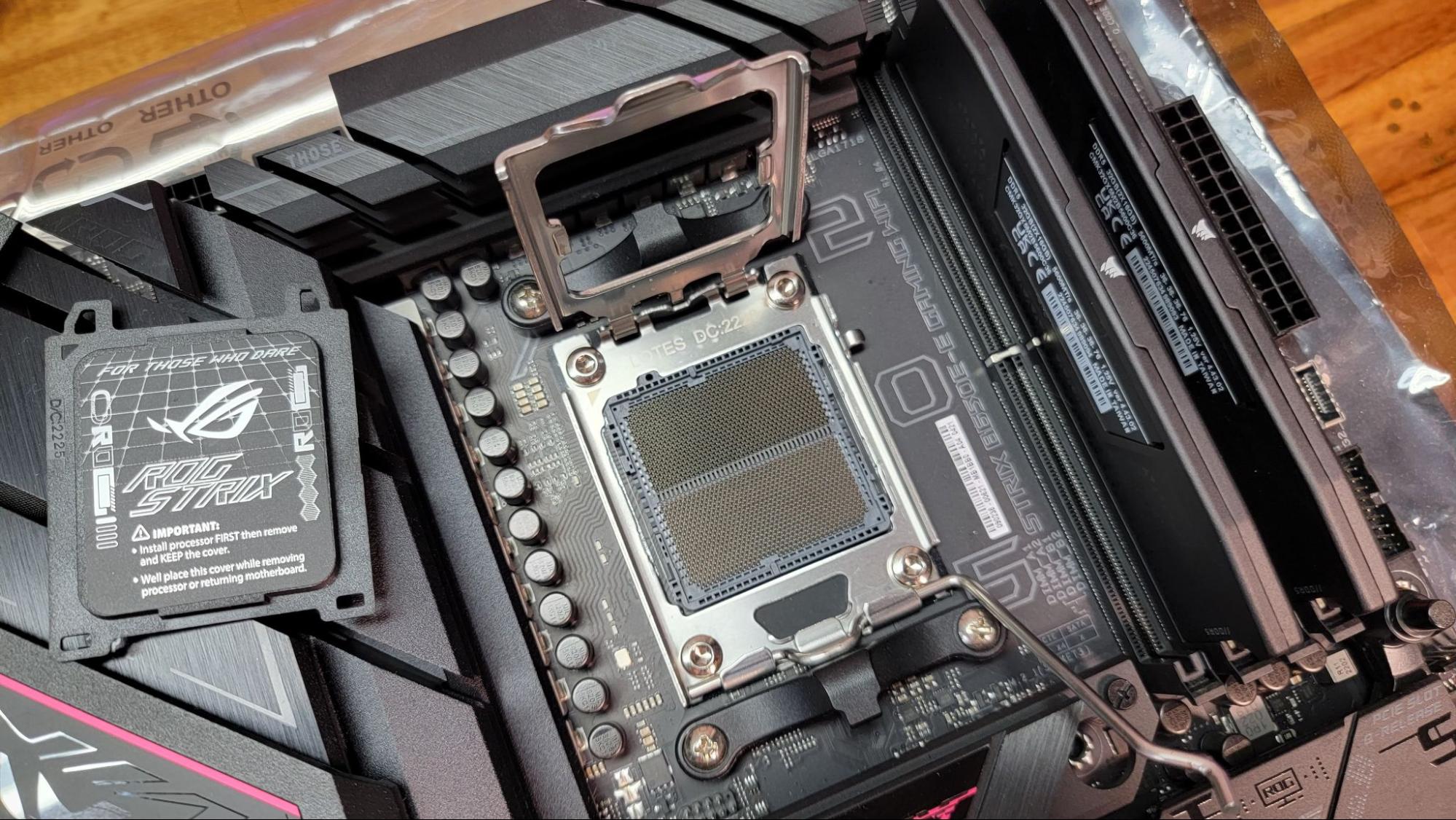
It should be noted that recent Intel motherboards and AMD’s latest AM5 platform feature CPU-connecting pins integrated into the socket, whereas AMD’s AM4 and earlier platforms have the pins located on the underside of the CPU. In the context of this narrative, this distinction holds significance primarily due to the increased susceptibility of older AMD CPUs to damage through pin bending. Therefore, when installing an AM4 CPU (such as Ryzen 5000 or older), individuals should exercise extra caution in their handling and installation.
Irrespective of the platform being utilized for the build, a discernible arrow or triangle is present in one corner on the upper surface of the CPU. It is imperative that this marking aligns with the corresponding triangle on the socket or socket cover during installation.
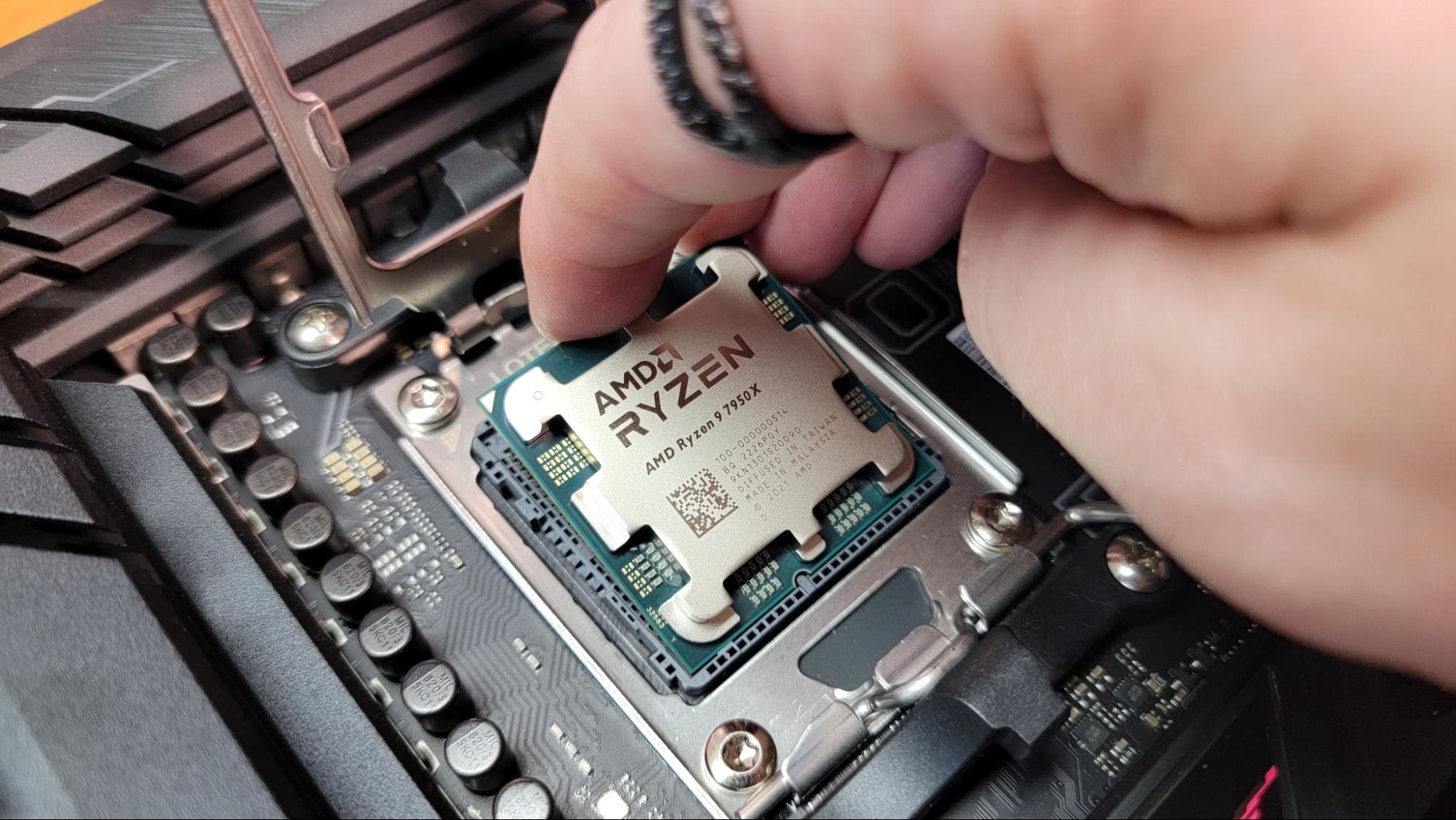
Don’t attempt to install a CPU with the arrow facing the wrong direction, or you could damage your chip, your board, or both! Once your CPU and socket are properly aligned, you can (gently) drop the chip in place, and it will settle into the socket under its own weight. If it doesn’t, pick up the CPU and reseat it. Don’t force the processor into the socket or you’ll almost certainly damage something.
Once you’ve got the CPU settled correctly in the socket (check to see that it sits evenly, so that it isn’t sticking up on any one side), drop the retaining bracket down over the edges of the processor, then press the tension lever back down.
Note that on Intel 12th and 13th Gen boards in particular, this may require a surprising amount of force, to the point that socket bending is a known issue, for those who often remove and reinstall processors in their motherboards. This shouldn’t be a concern for a regular build where you install the CPU once or perhaps twice. Just know that you’ll have to push the retention lever down pretty hard to get it to slip under its retention tab. So long as you’ve double-checked that your CPU is correctly seated before this, there’s no cause for concern.
Note that the above instructions pertain to the mainstream platforms for AMD and Intel. Enthusiast platforms like Intel’s Xeon (or older Core X) and AMD’s Threadripper have different / more complex CPU installations, with the Intel chips involving two levers and Threadripper requiring Torx screws and a slide-in plastic bracket. Given the cost and added complexity, we would not recommend either of these for your first PC build.
The Cooler
Many processors are bundled with coolers in their packaging. If an individual is not engaging in extensive overclocking, those included coolers may suffice. However, many builders also opt to purchase more robust aftermarket coolers, which tend to offer improved performance in terms of both cooling efficiency and noise reduction, and they often boast a more aesthetically pleasing design.
If one decides to utilize the stock cooler, they will discover that it comes pre-applied with thermal paste, a feature shared by numerous AIOs and aftermarket coolers.
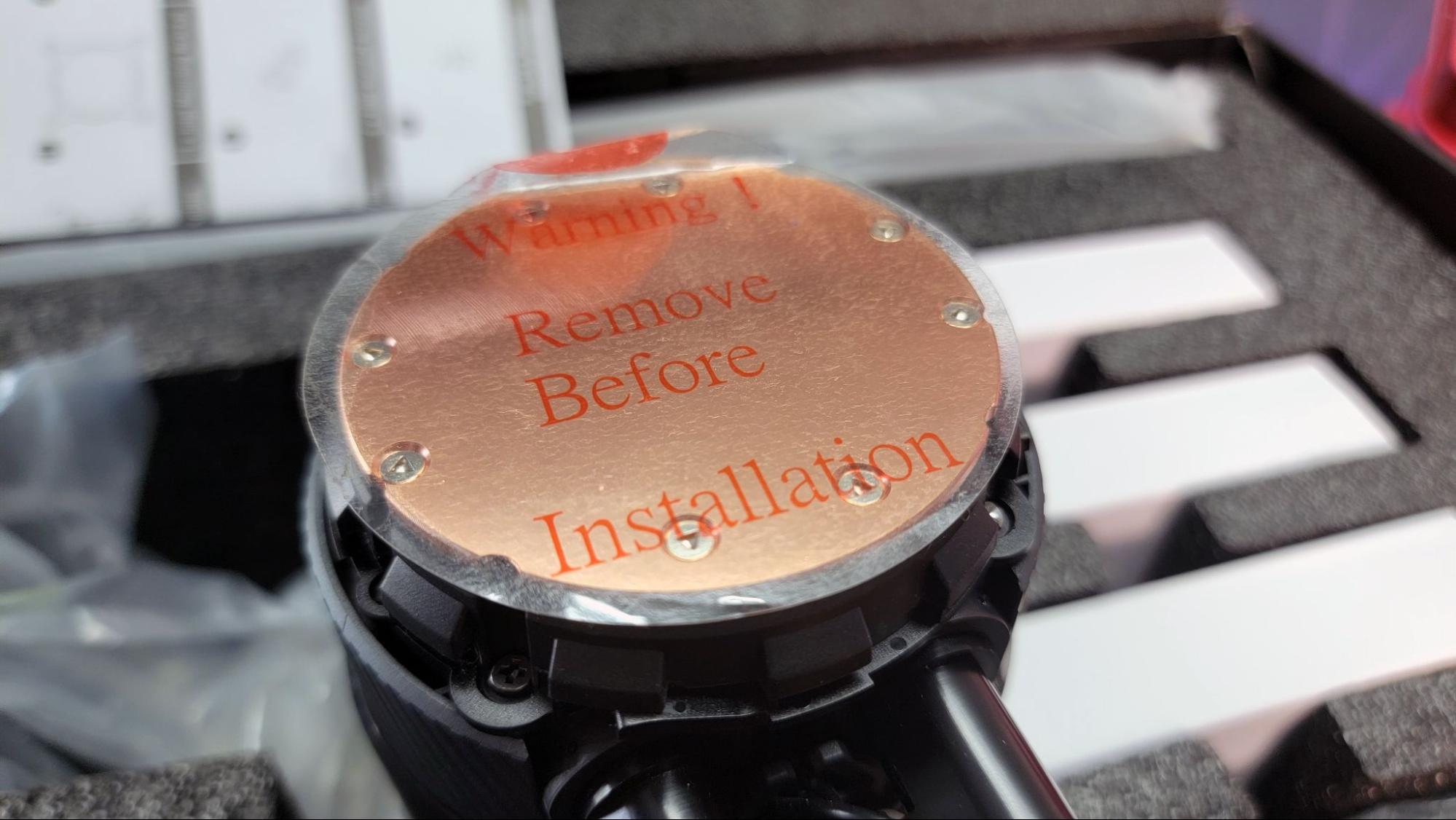
Regardless of whether there is pre-applied paste on your cooler or not, don’t forget to peel the protective film off the cold plate / paste area before installing the cooler. If you skip this step, you’ll have to tear half of your system apart later when you realize your CPU temperatures are abnormally high.
While pre-applied thermal paste is increasingly common, you’ll still often need to apply your own thermal paste atop the CPU. The tube that comes with your cooler will work well enough, but if you want even lower temperatures, consider checking out our list of the best thermal paste we’ve tested.
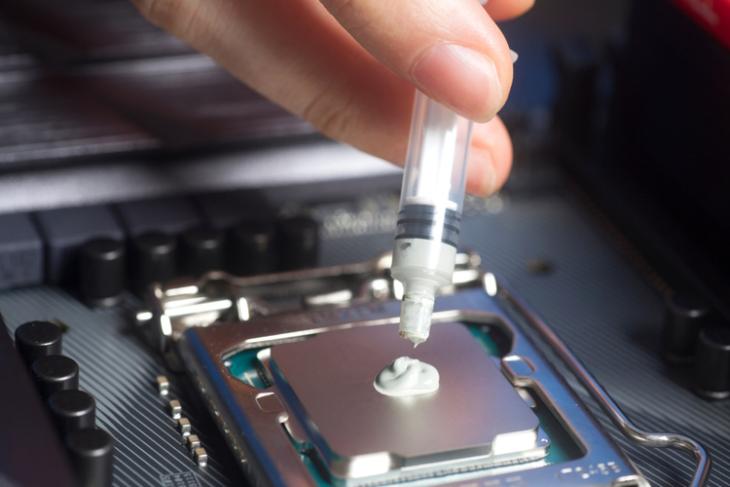
One doesn’t require an excessive application of thermal paste. It is advisable to apply a pea-sized quantity, roughly measuring about 3 mm, to the center of the CPU for AMD’s latest chips. Conversely, for recent Intel CPUs, characterized by their longer design and heat-generating components situated less centrally beneath the heat spreader, a pattern consisting of five smaller dollops is recommended. Experienced overclockers and seasoned builders may have their unique methods, but it’s essential to exercise caution not to apply an excessive amount of paste. This will prevent any excess from extruding onto the socket and the surrounding PCB.
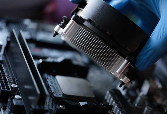
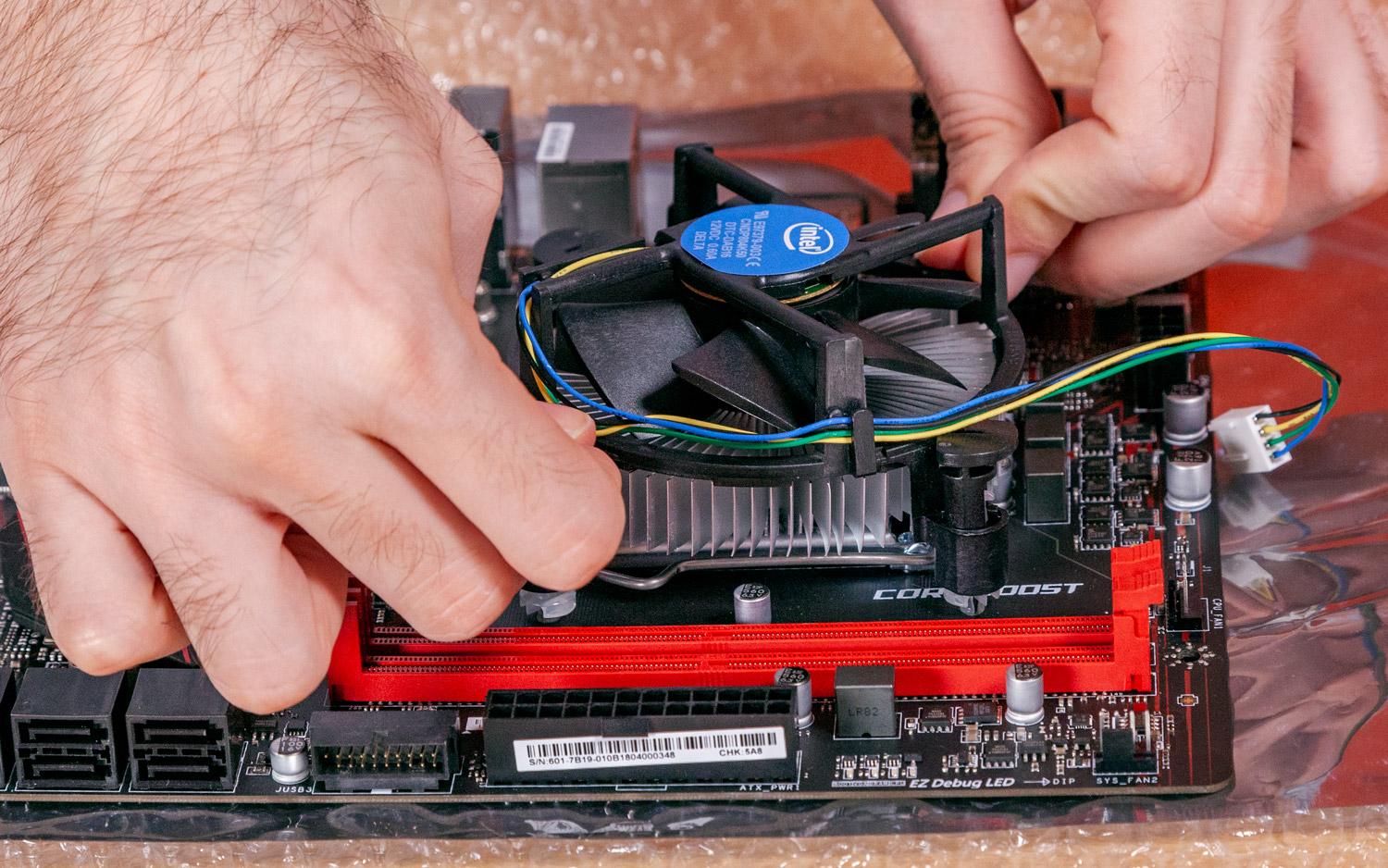
Stock coolers designed for Intel processors employ push pins that penetrate the motherboard’s holes. The advisable procedure involves applying pressure to opposite corners to ensure the even distribution of thermal paste and prevent uneven pressure on the CPU’s side, as is the recommended practice for securing any cooler. In contrast, AMD stock coolers feature metal arms that securely fasten into notches located on a plastic bracket positioned on either side of the socket. To affix aftermarket coolers onto AMD motherboards, it is often necessary to detach these plastic brackets.
Aftermarket coolers typically employ a variety of mounting methods, often involving more intricate procedures. Users are advised to refer to the instruction manual accompanying their cooler for guidance.
In some cases, it may be necessary to affix a sizable backplate behind the motherboard, a step that should precede the cooler’s installation within the computer case. Some computer cases feature designated cut-out areas behind the motherboard to facilitate the attachment of a CPU mounting plate after the motherboard is in place. However, the alignment of these cutouts with the CPU socket region is not always guaranteed. Effectively securing a metal plate behind the motherboard while simultaneously installing mounting hardware within the case demands a considerable degree of manual dexterity and patience.

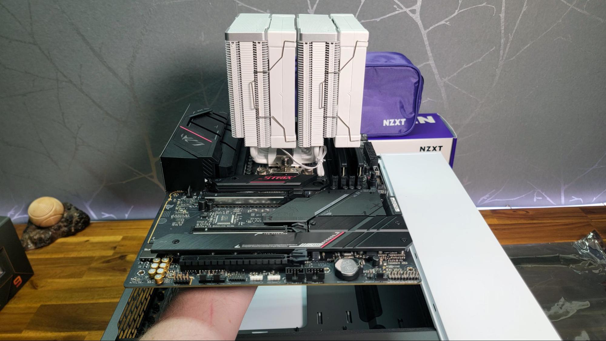
It should be noted that when installing a large air cooler that extends over the RAM slots, such as the DeepCool AK620 used in the build depicted in many of these photos, it is advisable to perform the subsequent step of memory installation before mounting the cooler. This precautionary measure should ideally be taken prior to commencing the PC assembly process.

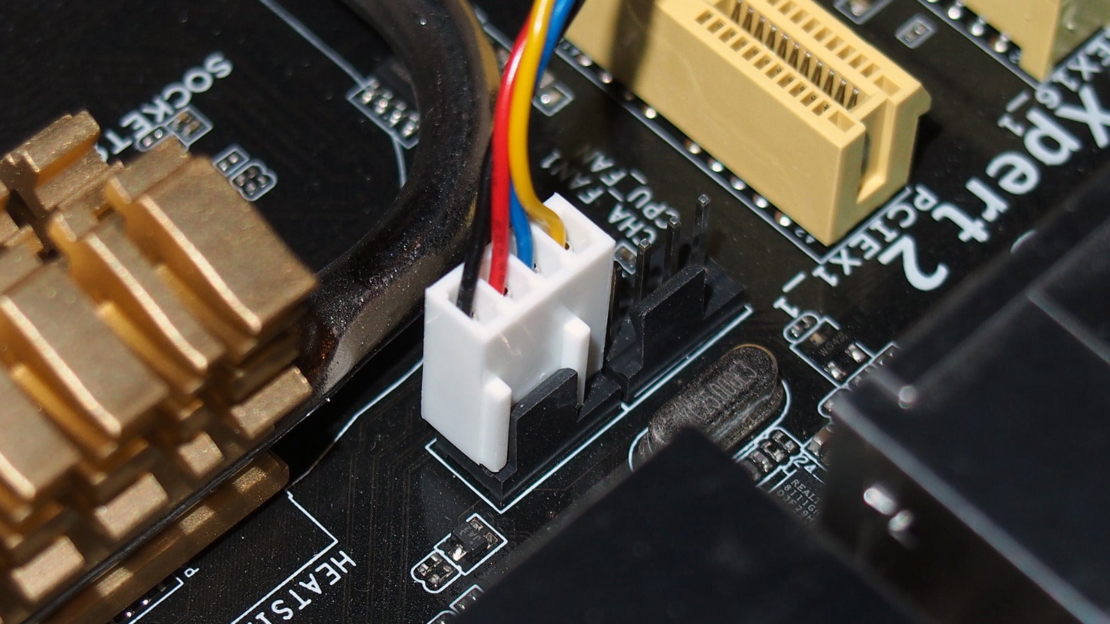
Once the cooler is installed, the user should proceed to plug the CPU fan connector into its corresponding header on the motherboard. Typically, this header is located in close proximity to the CPU socket and is labeled as “CPU_FAN.” In the case of a larger cooler equipped with two fans, the user will also be required to connect the second fan, usually found on a nearby header labeled “CPU_AUX.” Furthermore, if the user is installing a liquid AIO cooler, it is essential to connect the pump as well. Many motherboards provide a dedicated “CPU_PUMP” header connector for this purpose.
Memory
Installing RAM becomes a straightforward task, irrespective of whether one’s motherboard utilizes the modern DDR5 or the more budget-friendly DDR4. Initially, when inserting two RAM sticks into a motherboard with four slots, it is essential to consult the motherboard’s manual to ensure correct placement of the DIMMs. Incorrect slot placement may result in suboptimal performance or the motherboard and operating system failing to recognize one of the sticks.
Once the user has determined the appropriate RAM slots for installation, they must confirm that the latches for each memory slot are in the open position. Depending on the motherboard model, some may feature latches on both sides of a RAM slot, while others may have a latch on just one side, with the opposite end being fixed in place.
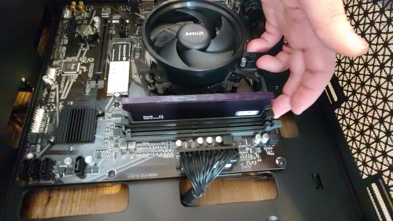
The user should proceed to open the latches and carefully position each DIMM over the slot. Alignment is crucial, and the small divot on the bottom of the RAM stick should align with the corresponding bump on the motherboard. If the divot does not match up, simply flip the RAM stick around. Gently insert the stick into the slot and apply pressure to both edges of the DIMM until it securely snaps into place, causing the latches to close automatically.
While a certain amount of force is required during this process, if any difficulties arise, the user should ensure that they are not attempting to insert the module incorrectly or that any ends are not aligned properly with the slot. It is worth noting that in some instances, the latches may not fully close on their own. In such cases, after confirming that the RAM sticks are fully seated in their slots, the user can gently push any remaining latches into the closed position.
M.2 SSD
For anyone utilizing an M.2 SSD, the opportune moment for installation presents itself at this juncture. Delaying this task may lead to potential obstructions from other components down the line. Alternatively, one may opt to undertake this step at an earlier stage, given that an M.2 drive’s compact form factor allows it to lie flush against the motherboard without interfering with other elements.

When an individual’s motherboard features multiple M.2 slots, a critical initial step involves determining the appropriate slot for installation. Depending on the specific M.2 drive type, such as SATA or PCIe/NVME, and the compatibility of the motherboard slots, certain M.2 drives may not function or physically fit in particular M.2 slots. Furthermore, it is essential to ensure that high-speed PCIe 4.0 or 5.0 SSDs are placed in the motherboard’s fastest available slot. Consultation of the motherboard’s manual is recommended to ascertain the supported drive types for each M.2 slot. As a general guideline, if the boot drive is a PCIe drive, it is advisable to install it in the M.2 slot nearest to the CPU.
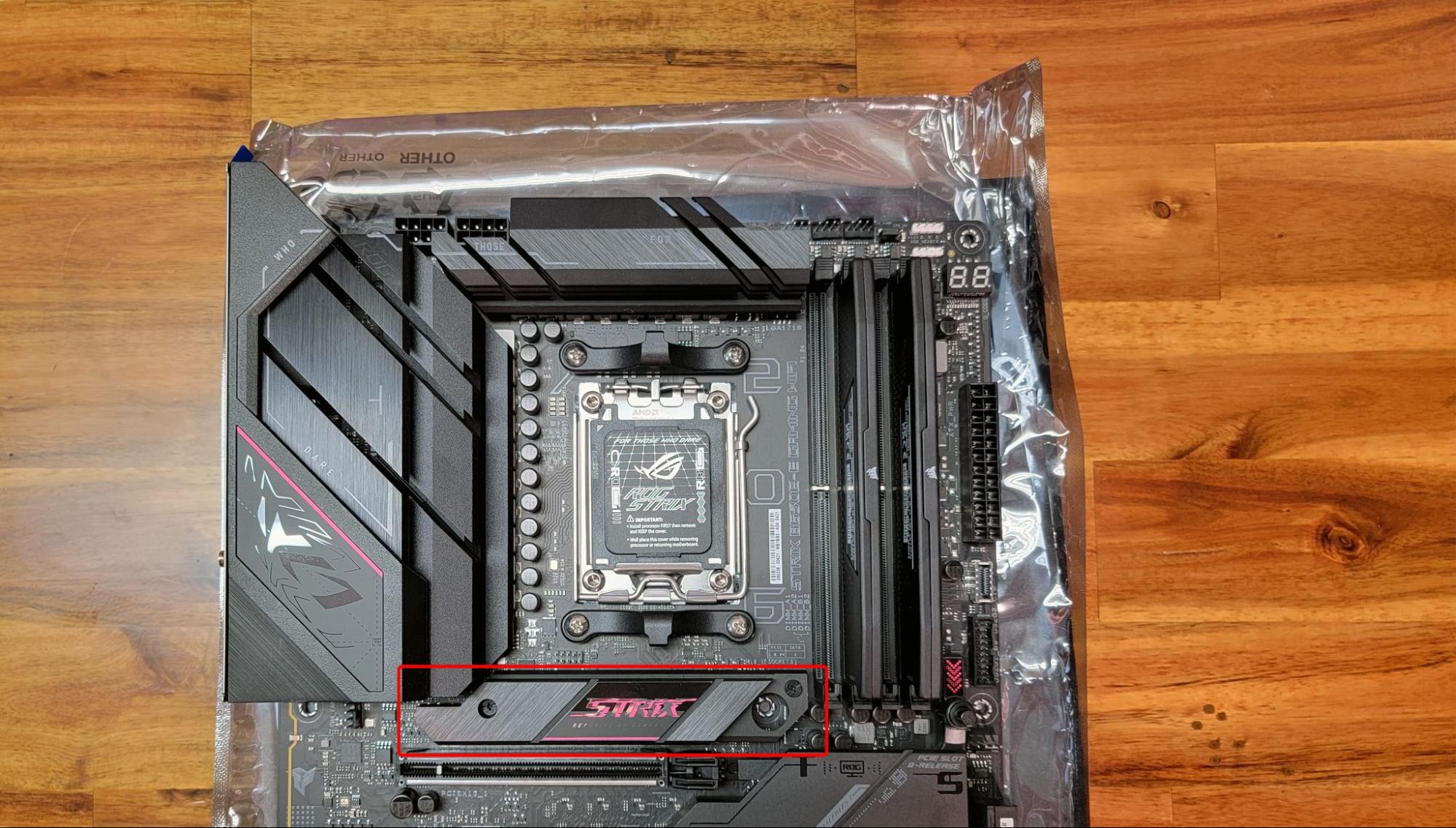
Once an individual has identified the desired slot for use, they may encounter the necessity to eliminate a heatsink or cover in order to access the M.2 slot and proceed with the installation of their drive. This typically entails the removal of one or two small screws, followed by the detachment of the heatsink, thus rendering the M.2 slot prepared to accommodate their SSD.
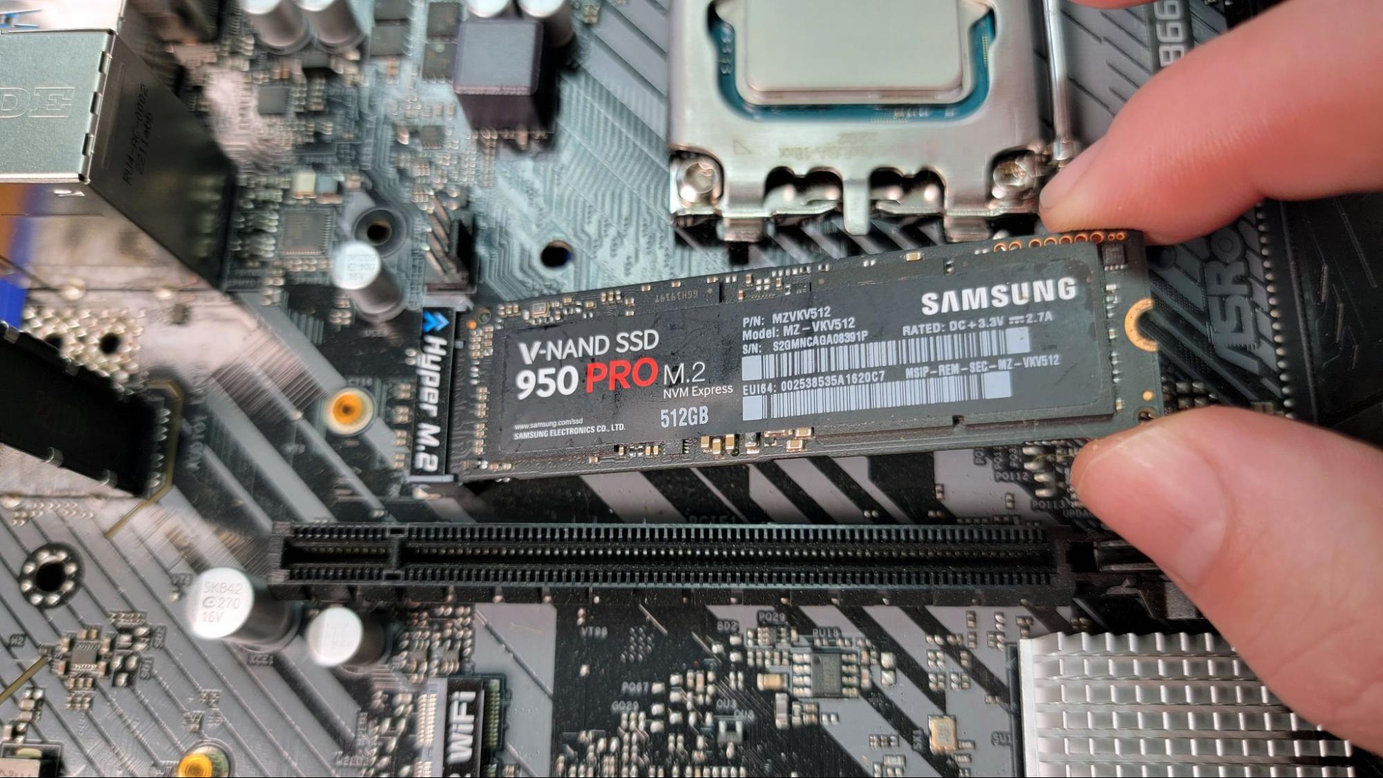
If the SSD is already installed, one should remove the screw located opposite the M.2 slot and proceed to insert the SSD into the M.2 slot at an angle. It is essential to ensure that the notch aligns with the slot, akin to the installation of RAM. In the event that the notch does not align, it is advisable to consult the manual for compatibility details regarding the drive and the slot.
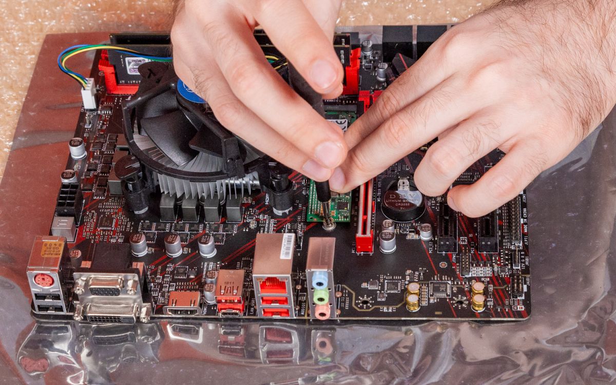
They slowly lay the SSD flat and secure the mounting screw. The tiny screw’s ease of dropping becomes another incentive to install M.2 drives prior to placing the motherboard inside the case. Some high-end boards feature a small plastic tab that can be conveniently pushed aside during drive installation, subsequently slid back to firmly secure the drive in place.
Once the drive is installed and securely fastened with a screw or tab, the user should reposition the heatsink to its original location atop the drive, unless the drive already includes its own heatsink. It is essential to ensure that when reattaching the motherboard heatsink above the drive, the user removes the protective plastic sheet covering the thermal pad, situated on the inner surface of the heatsink, similar to the process followed for the CPU cooler.
Putting the Motherboard in the Case
Having completed the construction of the core platform, excluding the graphics card, which will be addressed at a later stage, the next step involves the installation of the CPU, RAM, and motherboard equipped with an SSD into the case. If the side panels of the chassis have not been removed, they should be taken off. It is worth noting that most cases utilize thumb screws to secure their panels, simplifying the removal process.
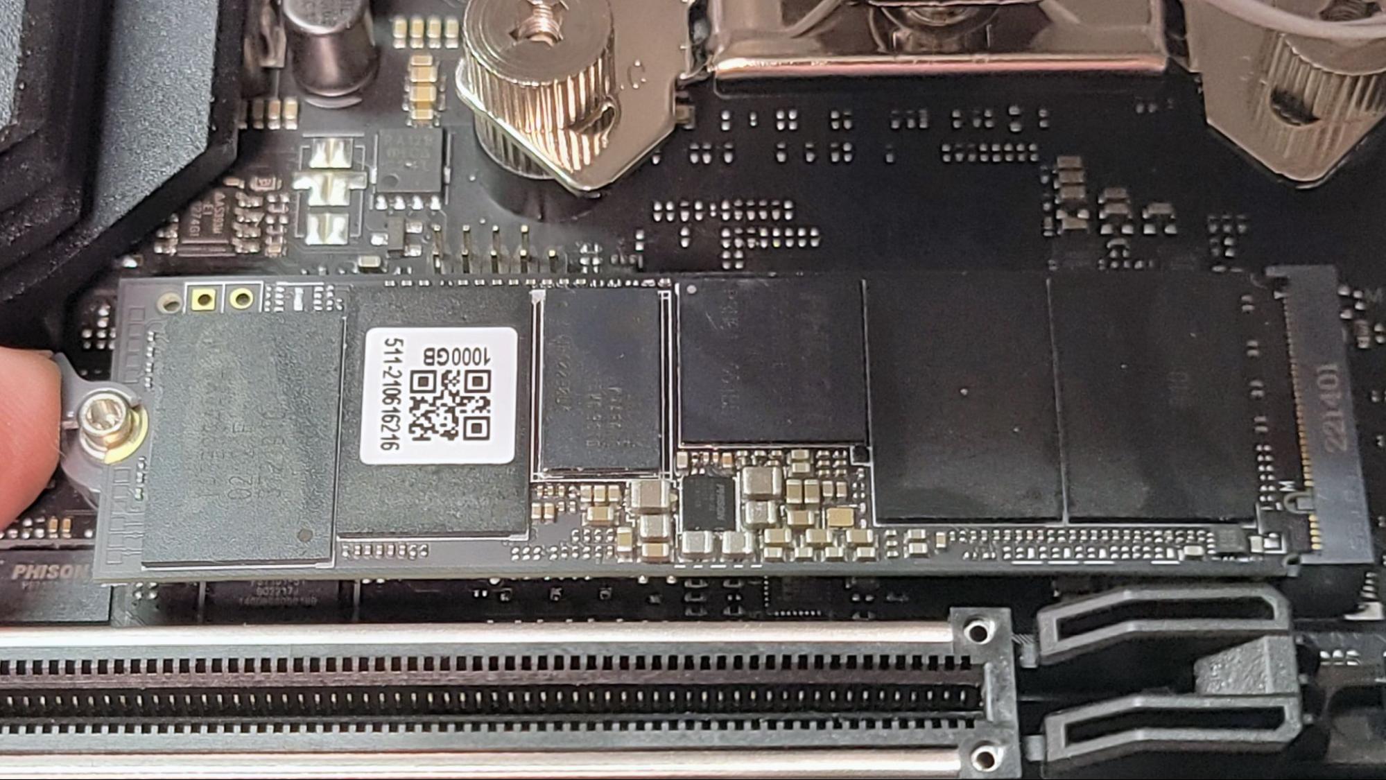
Standoffs
To begin, the user should collect the standoffs provided with their case, typically found in a separate bag. These standoffs should then be located and positioned appropriately for installation. The holes in the board mounting area within the case will typically be labeled according to the selected motherboard’s size.
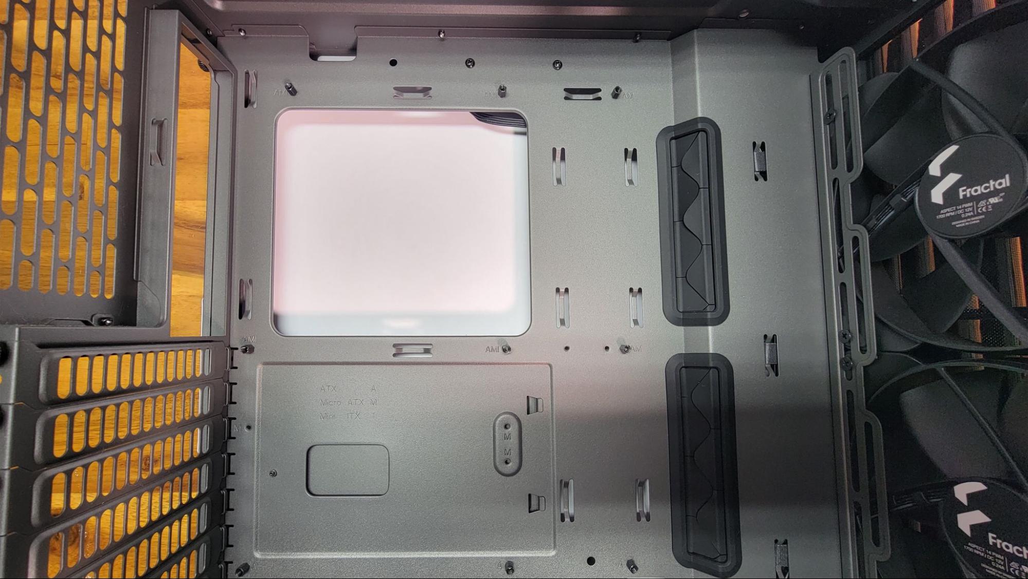
In many cases, standoffs come preinstalled, potentially allowing individuals to bypass this step. If, however, these standoffs are incorrectly positioned for one’s motherboard, they can utilize needle nose pliers to remove them and then securely fasten them into the appropriate holes for the specific motherboard.
Additionally, certain cases will come equipped with a designated standoff or post that aligns with the central mounting hole of the motherboard, provided it follows the ATX standard. This feature greatly aids in positioning the motherboard correctly within the case. After inserting the motherboard into the case with the post protruding through this hole, most of the remaining screw holes should align (or come close to aligning) with the motherboard’s standoffs.
It is advisable to refrain from fully installing and screwing the board in place at this stage, particularly if the IO shield is not pre-installed on the motherboard.
I/O Shield
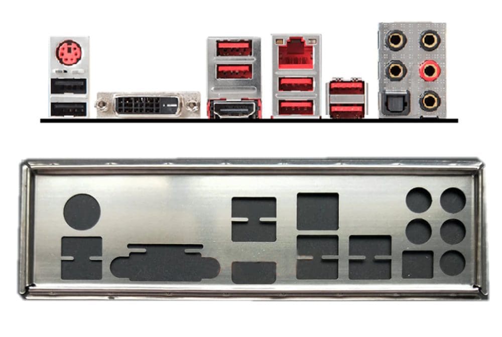
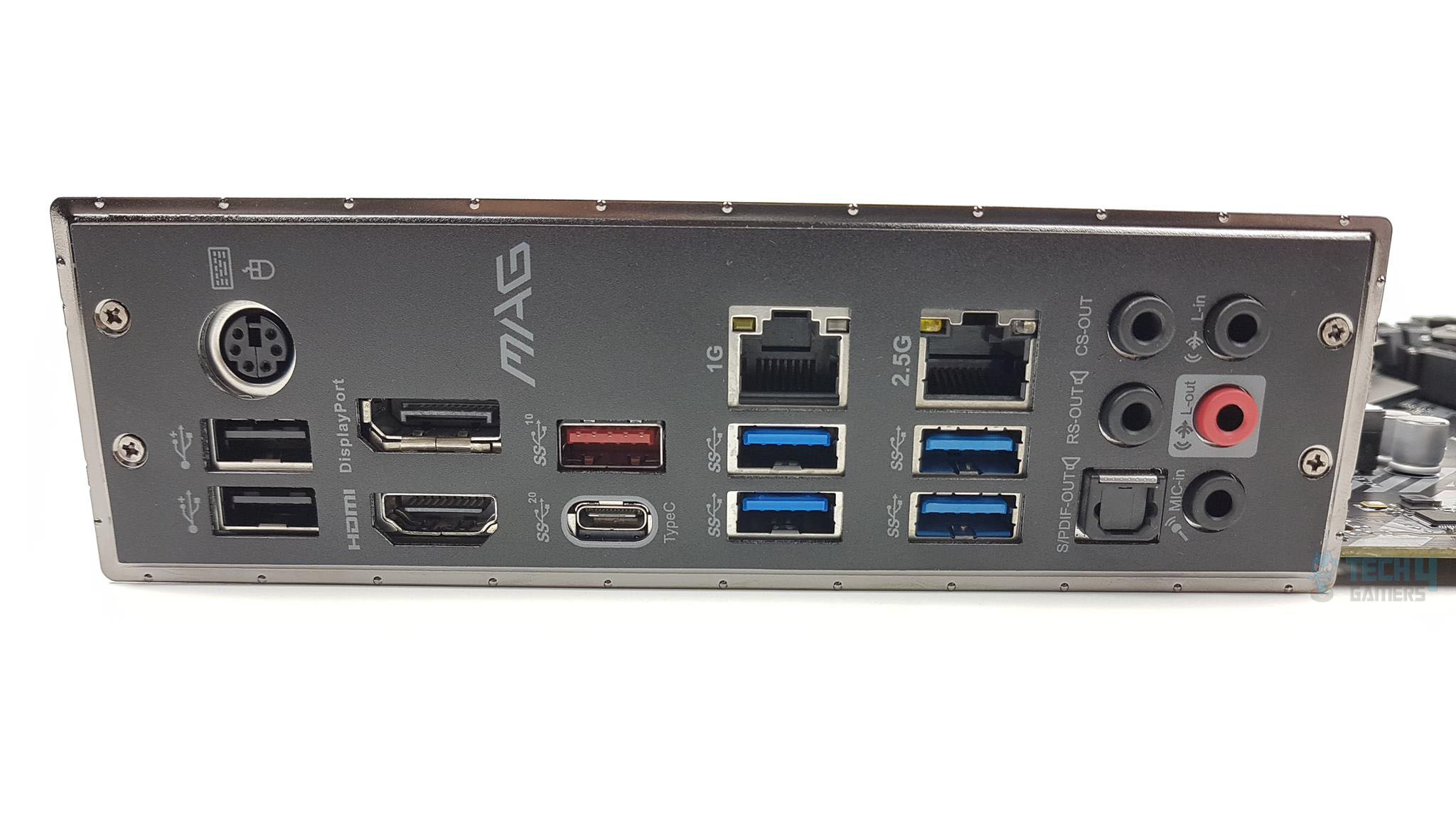
The IO (input/output) shield, which encompasses the vicinity of the rear ports, is included with the motherboard. One must ensure that the shield is correctly oriented before installing the motherboard into the chassis. This ensures that the motherboard’s external ports align with the corresponding holes once both components are in place. Applying some force is necessary to securely fasten all four corners. Caution should be exercised due to the presence of sharp edges (hence the need for band-aids) and potential metal obstructions that may impede the ports, particularly when dealing with a budget motherboard.
It should be noted that in the case of mid-range to high-end motherboards manufactured in recent years, the IO plate may come pre-attached to the motherboard, eliminating the need for this step. To determine whether this is the case, one should inspect the area housing the USB and audio ports on the motherboard. If the ports appear uncovered, lacking any labeling or concealment of the port housings, manual installation of the plate is required. Conversely, if only the open ends of the ports are visible, encircled by labels indicating their respective functions, the plate has been pre-installed.
Installing the Motherboard
Now it is finally time for the user to install the motherboard into their case. They should ensure that the holes on the motherboard align with the standoffs that have been previously installed and that the ports match up with the cutouts on the IO shield.
Now it is finally time for the user to install the motherboard into their case. They should ensure that the holes on the motherboard align with the standoffs that have been previously installed and that the ports match up with the cutouts on the IO shield.
Once the board is inserted, the screws should be threaded through the holes on the motherboard and secured into the standoffs to firmly anchor the motherboard in its designated position.
Once this task is completed, it becomes an opportune moment to upright the case, as many subsequent steps in the building process are more straightforward in this orientation.
Adding the Power Supply and Traditional/SATA Storage
Now, there are a few components that attach to the case rather than the motherboard.
Power Supply
The power supply, often referred to as the PSU, is typically situated on the rear side of the case. In some instances, it may be positioned at the top, but more commonly, it is located at the bottom to draw in cool air from beneath the chassis.
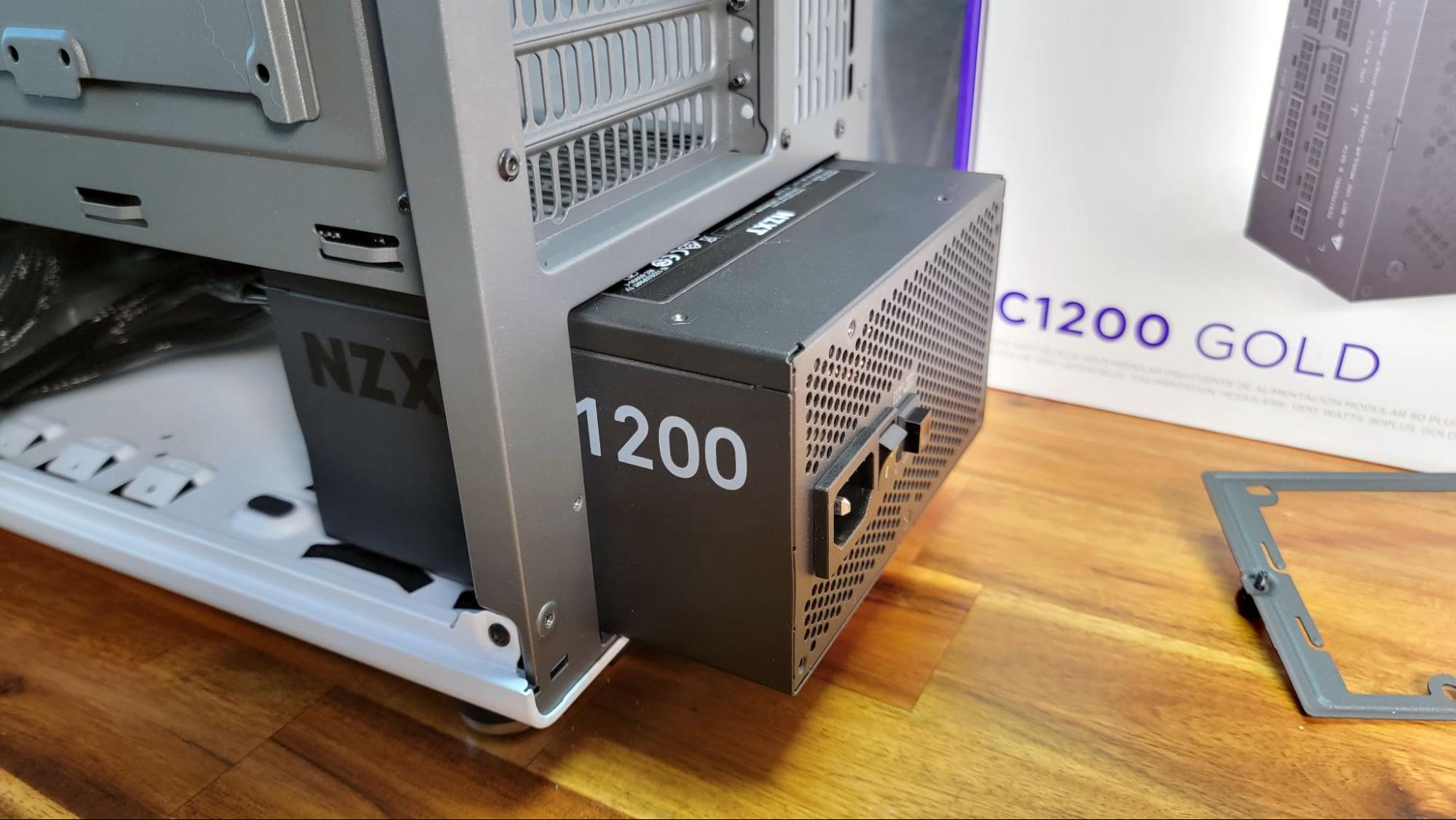
When utilizing a modular power supply, one should consider connecting all the necessary cables to the rear of the power supply before inserting and installing it. Otherwise, one may encounter difficulty when attempting to plug them in later from within the case, where the cable labels on the PSU may be challenging to discern. It’s important to note that if the power supply lacks removable cables, this issue does not apply.
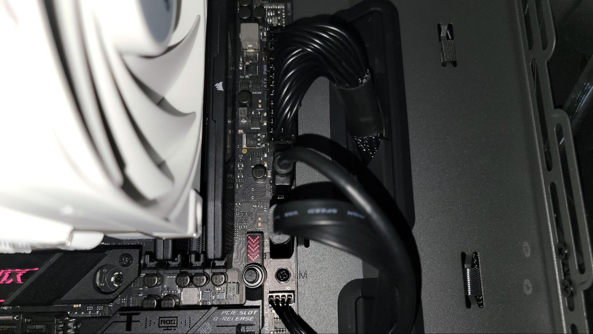
After placing the power supply within the case, the installation process is generally straightforward, involving the use of four screws on the back of the case to secure it. However, in some cases, it may be necessary to reinstall a bracket (as shown above, to the right) that must first be removed to accommodate the power supply’s insertion, after which the four mounting screws can be affixed. Once the PSU is securely installed, the 24-pin power connector and the supplemental/CPU power connector should be routed through the case and connected to the motherboard. Typically, the 24-pin connector is located near the center-right of the motherboard, while the PSU power connector is plugged into the top-left corner.
It is essential not to overlook this final step, as the installation of the supplemental CPU power connector can be challenging, given its placement near the top of the case. Moreover, as additional cables and components are introduced, the difficulty of this task increases, making it progressively more challenging to accomplish at a later stage. Failing to connect this component will result in the system’s failure to boot.
SATA Storage
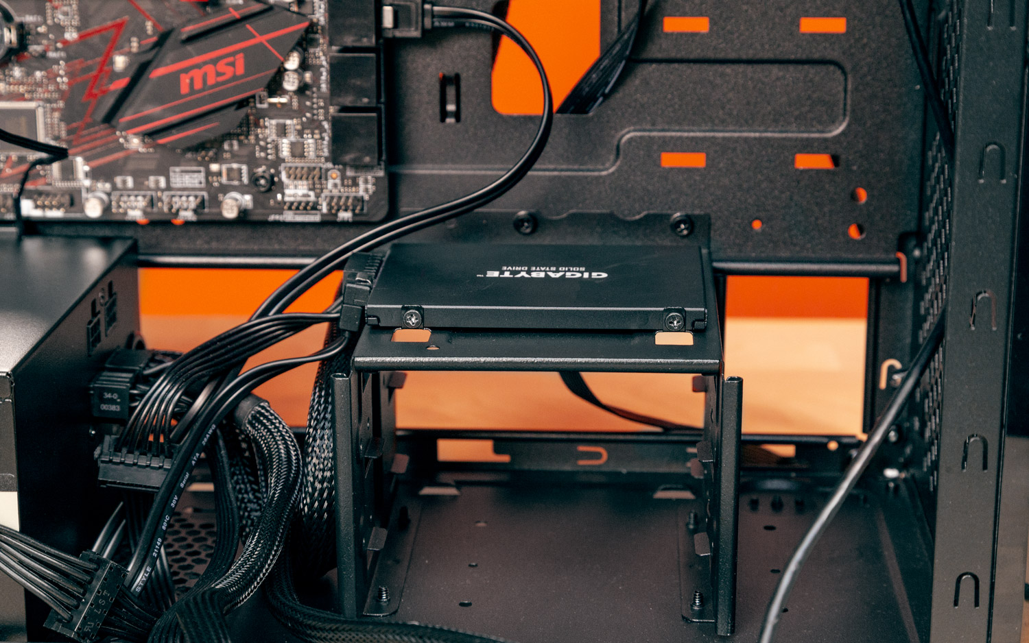
They previously incorporated M.2 storage into the system. Now, it is time to consider the addition of SATA drives, which may include a 2.5-inch SSD or hard drive, or a conventional 3.5-inch hard drive. The user should connect the SATA data cable to both the motherboard and the chosen drive(s). Subsequently, the SATA power connector from the power supply unit (PSU) should be connected to the designated drive(s). Finally, the user should secure the hard drive or SSD in the appropriate bracket and fasten it securely in place. It is worth noting that the specific bracket and drive mounting methods, as well as their placement, may vary depending on the chassis model being used.
Inserting the Graphics Card
To begin with, when installing a considerably large graphics card such as an RTX 4090 / 4080 or an RX 7900, or even a somewhat smaller card in a compact case, individuals should consider performing this task later in the process, once all other cables have been plugged in and cable routing or cleanup procedures have been completed. This precaution is essential because a bulky graphics card can obstruct easy access to the motherboard’s headers and connectors.
The installation of a graphics card is also an optional step. If an individual is utilizing an Intel or AMD CPU with integrated graphics and has no intentions of engaging in intensive gaming activities, the inclusion of a discrete graphics card may not be necessary or desired. However, it is important to note that many AMD CPUs, along with certain high-end Intel models, lack onboard graphics capabilities, necessitating the use of a graphics card to establish a connection and output to the monitor.
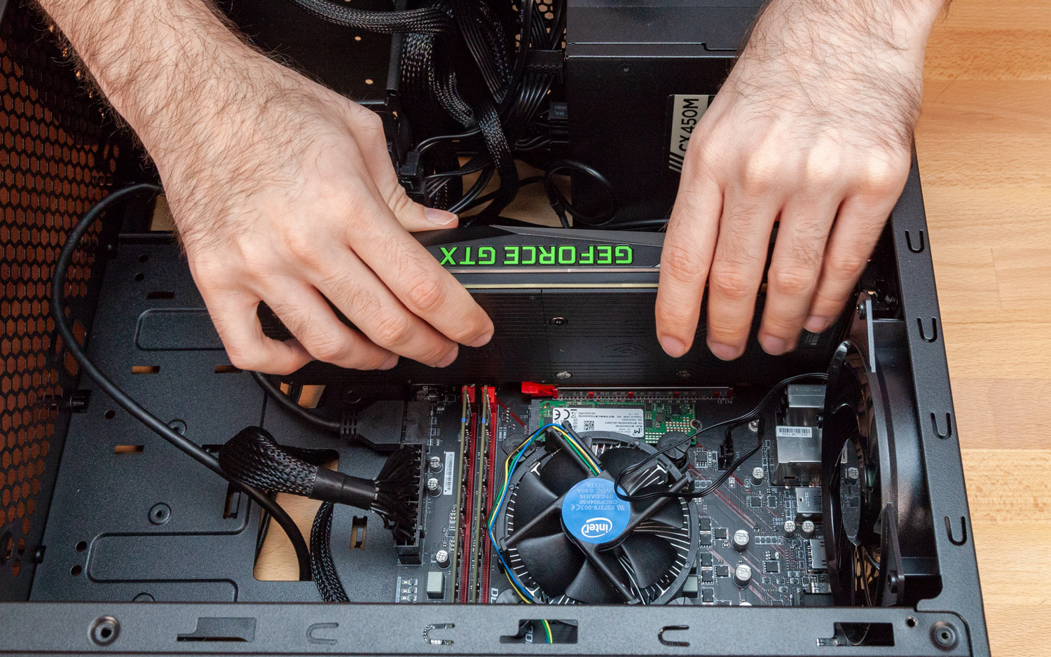
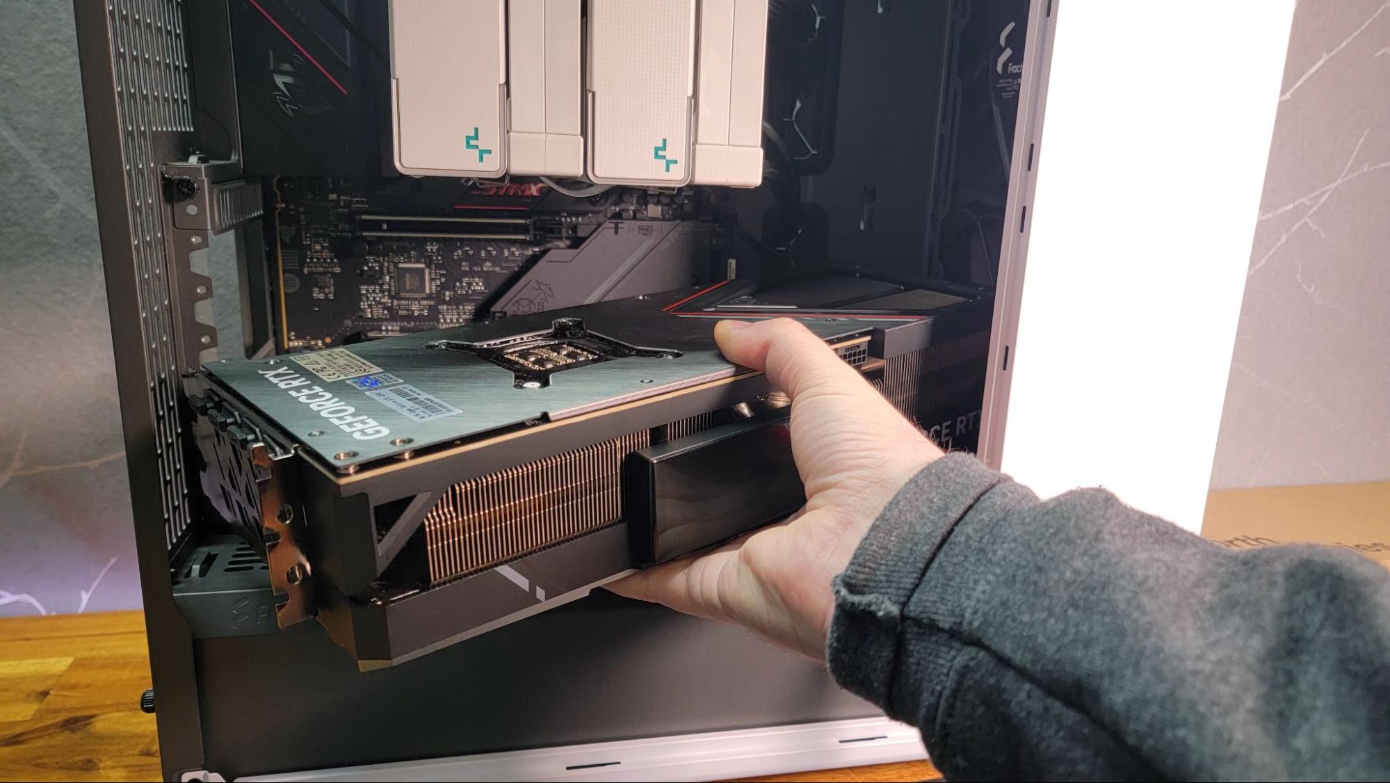
To proceed with the installation, the user should insert the GPU into the PCIe X16 slot on the motherboard, which is typically the longest slot available. In cases where there are multiple PCIe slots on the motherboard, it is advisable to use the topmost slot. If required, individuals should also connect the PCIe power connectors from the power supply to the graphics card. It is worth mentioning that lower-end graphics cards may not necessitate this power connection.
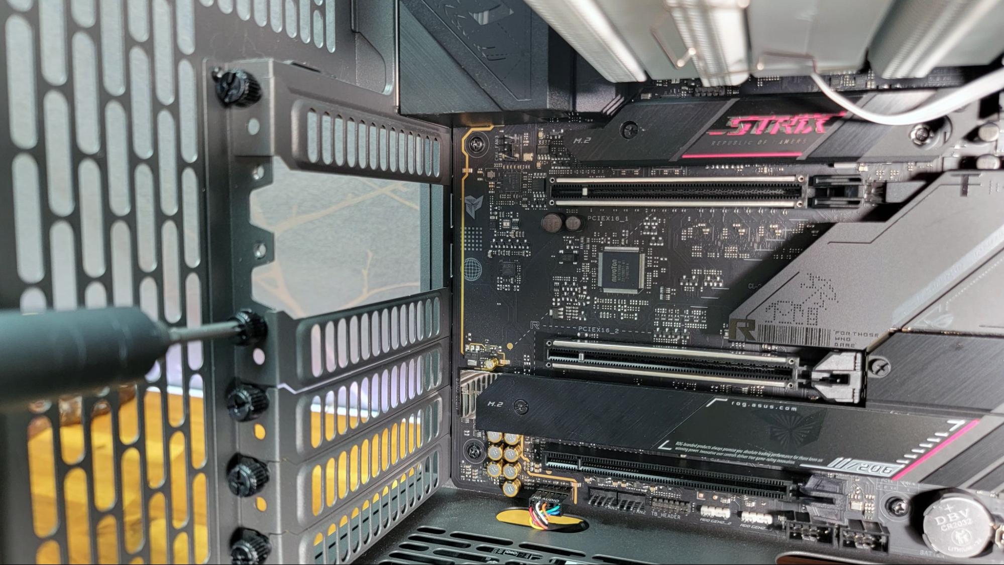
To install the GPU, one must typically remove certain slot covers located on the back of the case to expose the DisplayPort, HDMI, and any other graphics card ports. This enables the connection of monitors at a later stage. It is advisable to first align the graphics card with its designated slot within the case before proceeding with the installation. This precaution can help avoid the inconvenience of removing incorrect brackets and having to reinstall them later. Typically, the top expansion bracket does not require removal as it serves as a vestige from the era when a PCIe x1 slot occupied the space above the primary graphics card slot. Nowadays, this area is usually occupied by the primary M.2 connector, often concealed beneath a heat spreader.
The user should firmly insert the graphics card into the PCIe X16 slot located on the motherboard, which is the elongated slot closest to the center or top of the board. If the graphics card features PCIe power connectors on its front edge, these connectors should also be linked from the power supply to the card. It’s worth noting that low-end cards may not necessitate this step, as the PCIe slot can independently deliver up to 75 watts of power.
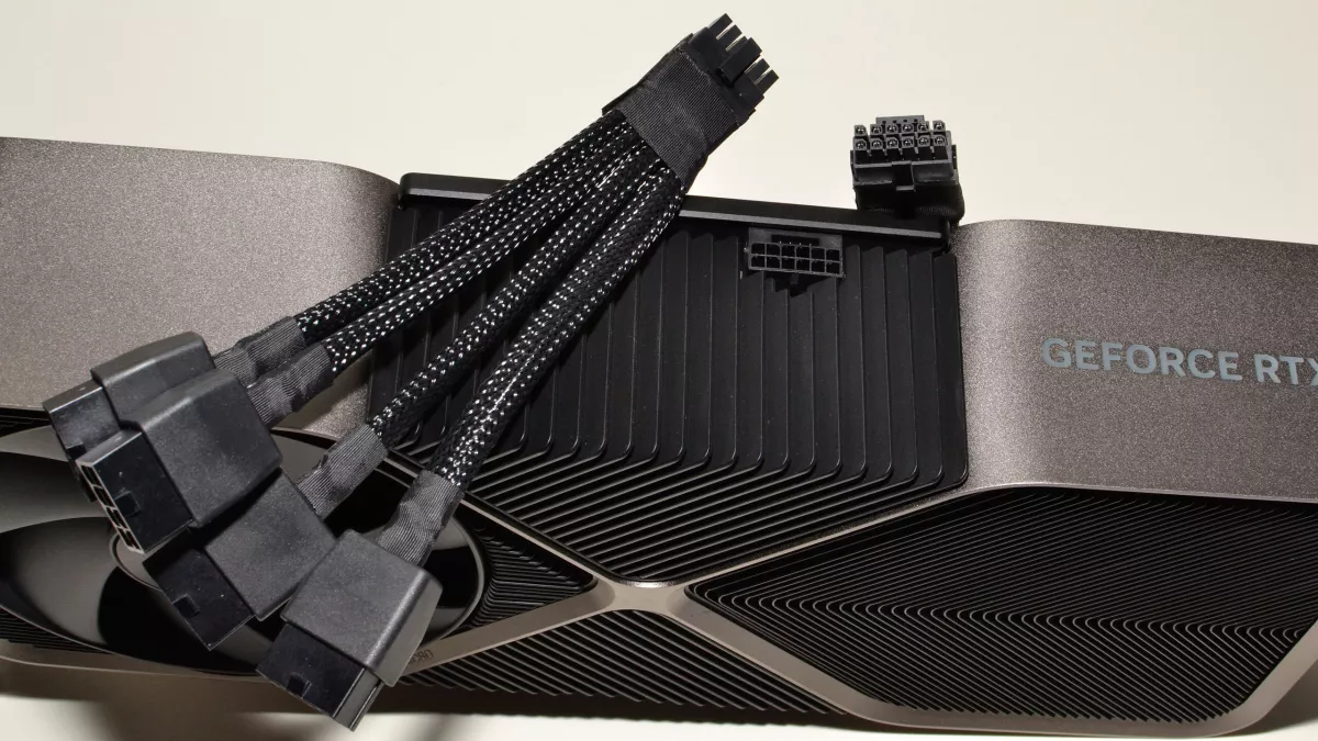
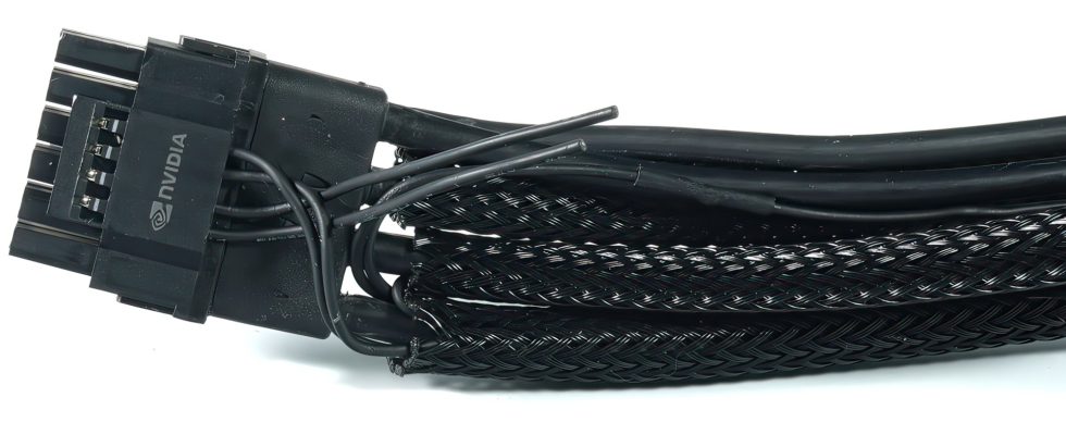
It should be noted that for high-end graphics cards, users will typically need to connect two or even three PCIe power connectors, occasionally utilizing an adapter provided with the respective graphics card.
For individuals undertaking the installation of an exceptionally high-end card, such as an RTX 4090, consideration may also be given to investing in an ATX 3.0 power supply. This particular power supply features a 12VHPWR connector designed specifically for the GPU, simplifying the connection process to a single cable.
Add a Wi-Fi Card (if necessary)
Most motherboards typically include an Ethernet port, and some also incorporate built-in Wi-Fi capabilities. Nevertheless, if an individual requires wireless connectivity and their computer lacks a Wi-Fi card, they will need to undertake installation in one of the available options, such as a PCIe slot, a short M.2 slot, or by connecting a USB Wi-Fi dongle. For those engaged in gaming activities, opting for an Ethernet connection is often considered the most reliable choice for ensuring a stable and uninterrupted connection.
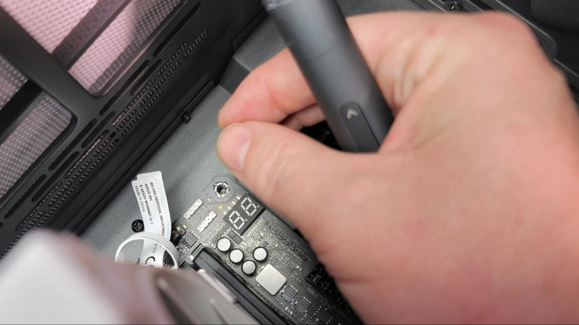
The Last of the Cable Connections
They were almost done with connecting the cables before attempting to power on the PC. They made sure that the connectors for any fans were properly plugged into the motherboard fan headers. Then, they proceeded to attach the front-panel audio cable, USB 2.0, USB 3.0, and 3.1/3.2 case connectors to the respective headers.
Individuals should consult their motherboard manual for this task, as the location and number of these components vary by motherboard model.
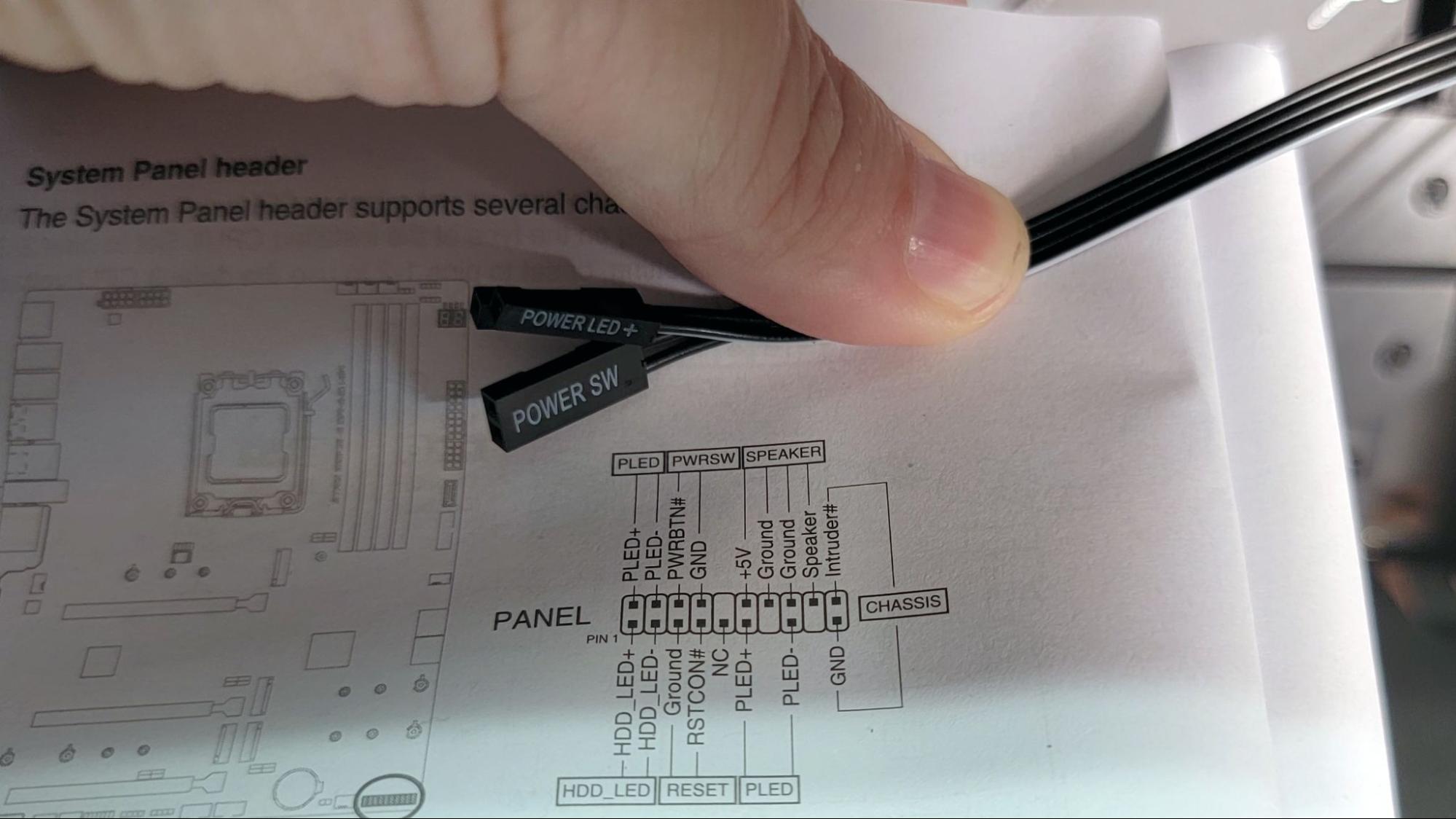
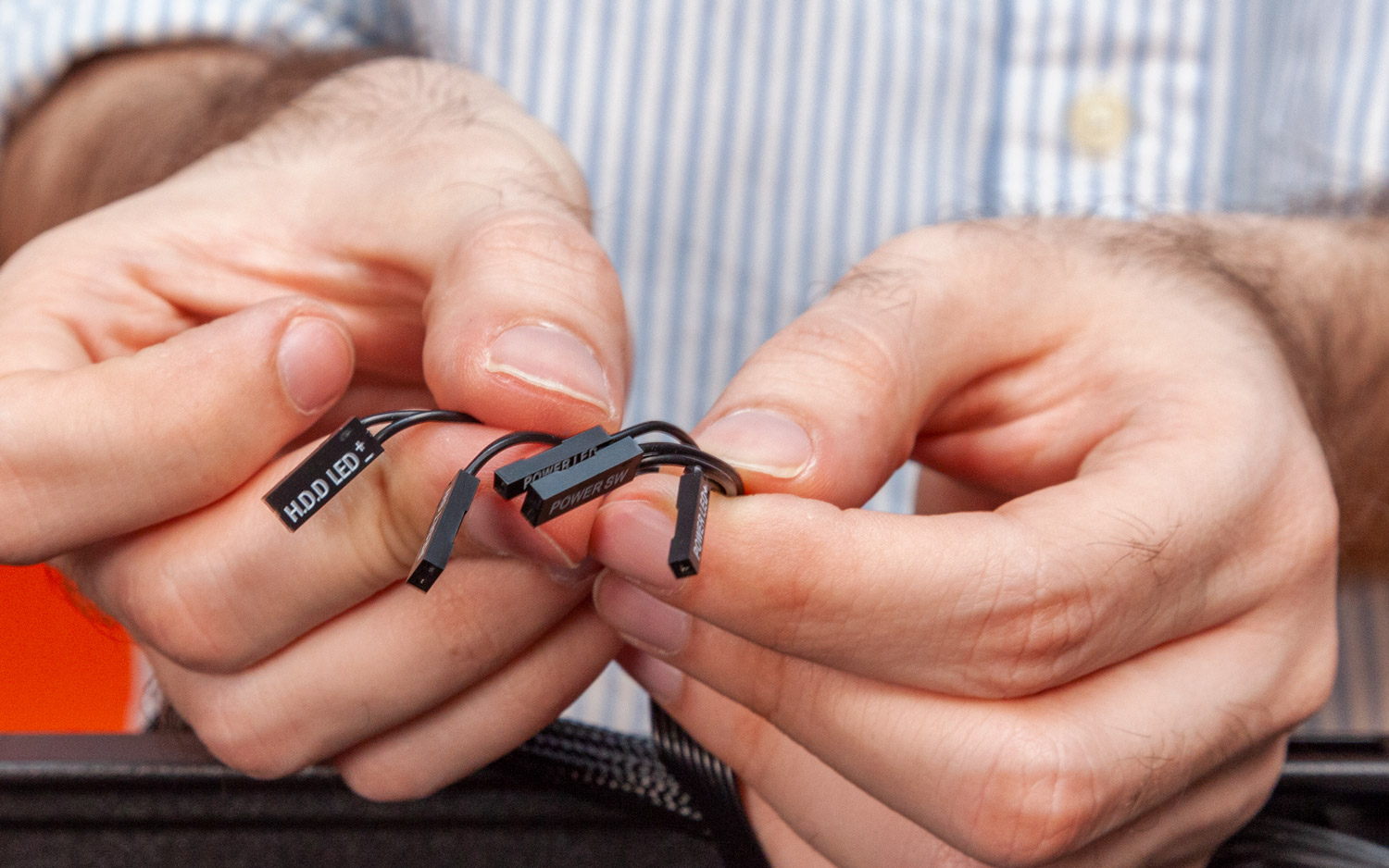
Lastly, the tiny front-panel connectors, including power, reset, HDD activity light, etc., must be connected to the appropriate pins on the motherboard, typically located in the bottom-right corner in the traditional orientation. One should consult their motherboard manual to determine the correct placement, as this may vary depending on the board’s make and model, although standardization has improved in recent years. Some cases may have fewer connectors, as reset switches and hard drive activity lights have become less common. Some cases may offer these connectors as a single block instead of individual pins, which is compatible with most recent-generation motherboards. Additionally, certain motherboards provide a block for plugging in the connectors, simplifying the installation process.
It is crucial to double-check the use of the correct headers. These components are small, and their labels can be hard to read, making it easy to make mistakes if one is not attentive. Furthermore, these connectors are prone to accidentally getting dislodged when handling cables or making adjustments inside the case after they have been connected.
For individuals with a large graphics card or a moderately sized card in a compact case, this is the optimal moment to proceed with the installation, including the attachment of any additional PCIe power cables, as previously mentioned.
Turn the Computer On

Upon completion of these steps, the individual should activate the power button on the monitor, followed by the activation of the power supply switch (located at the rear of the power supply). Finally, the user should press the power button on the PC itself. If all components are functioning correctly, the PC will initiate its Power-On Self Test (POST). As the operating system has yet to be installed, it is possible that the user may encounter an error message pertaining to a missing boot drive or may be directed straight to the UEFI/BIOS interface.
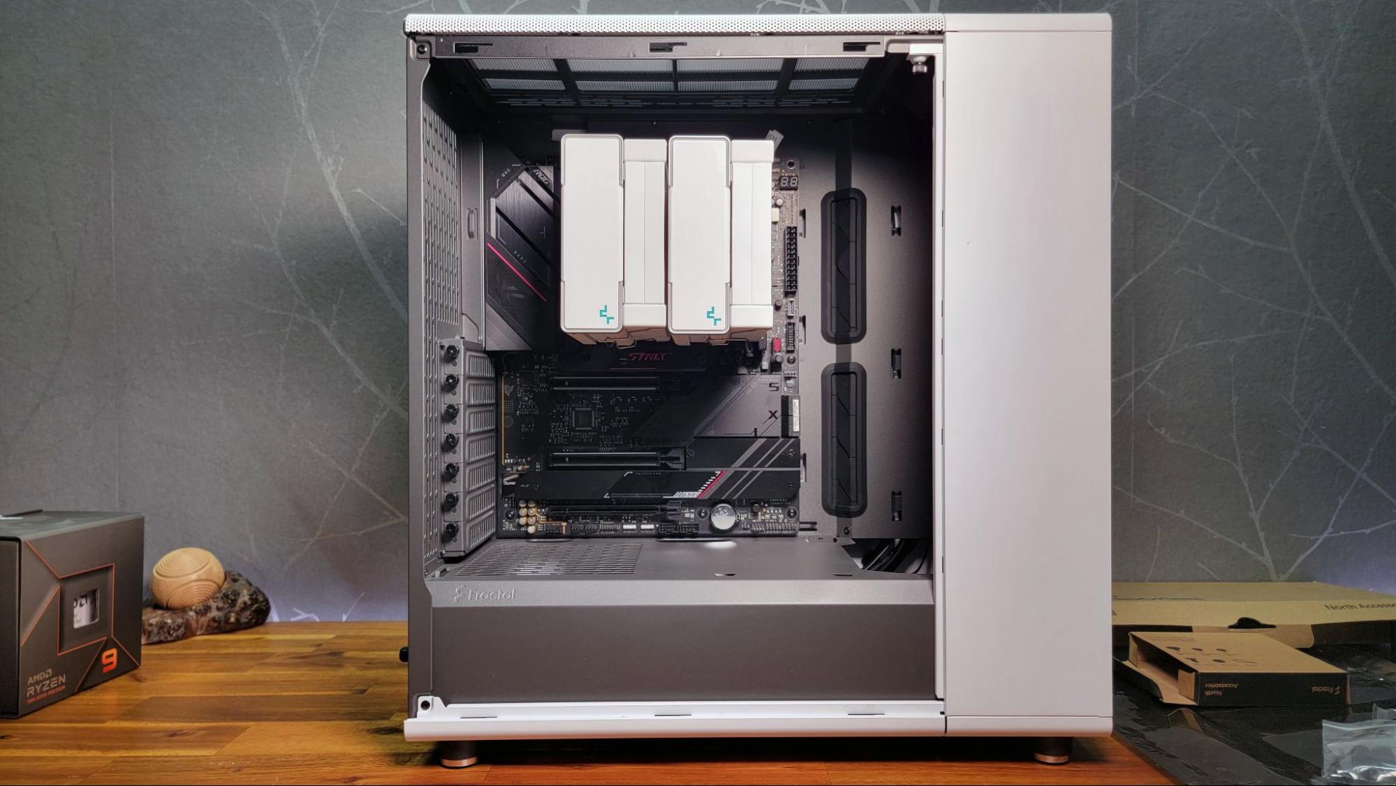
Cable Management
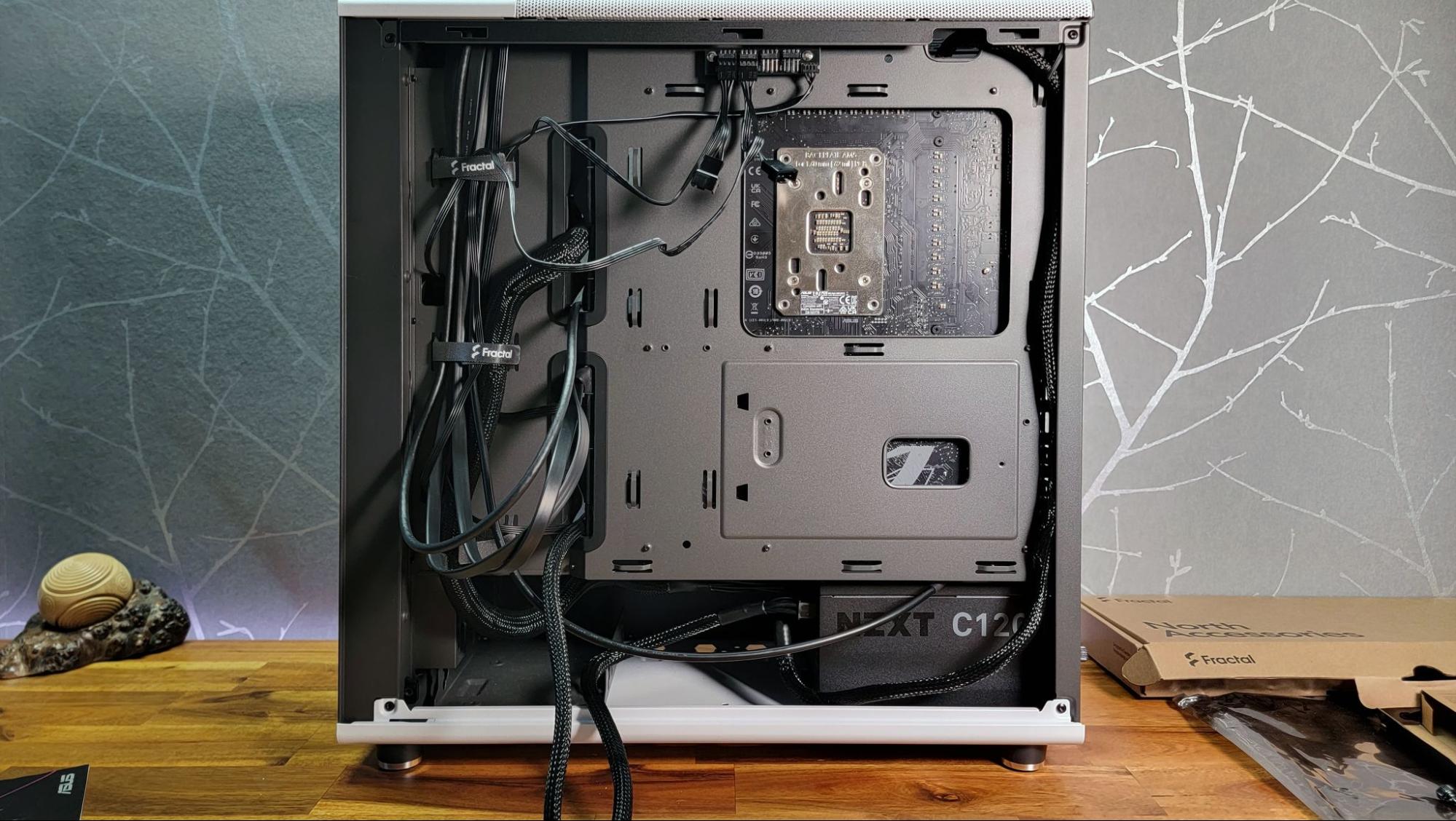
In this phase, one should focus on enhancing the interior aesthetics of the computer case while ensuring that cables do not obstruct airflow to the CPU or GPU. This step is best undertaken after confirming that the system boots successfully, as it avoids the need to dismantle carefully arranged wiring or cut multiple zip ties should component reseating or cable rerouting become necessary. Alternatively, one may choose to install the operating system before proceeding with this task.
Clean cable management becomes somewhat less crucial when the computer case lacks a glass side panel or window. Nevertheless, it remains beneficial to keep cables clear of airflow pathways, with the added advantage of achieving a tidy and visually appealing setup. To initiate this process, the user should power down the system, disconnect the power cable, and proceed with cable organization.
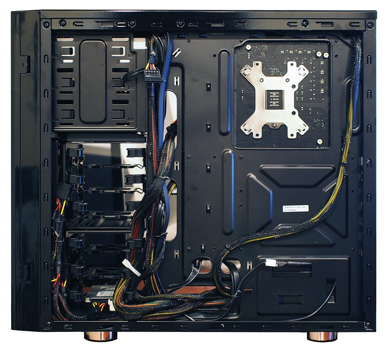
Routing cables through the back of the case during the build process is a recommended initial action for achieving a tidy build. At this stage, individuals typically push any surplus cable slack through the rear panel, employ zip ties to organize the cables, and subsequently reattach the side panels. While it is possible to invest several hours in meticulously perfecting cable routing, dedicating just 15 minutes to tidying up the cables following the system’s first boot can yield a significant visual improvement in the appearance of the final build.
Install an Operating System, Drivers and Updates

One would need to create a USB installation drive for Windows 11 or their preferred operating system. To do this for either Windows 10 or Windows 11, individuals should proceed to the Microsoft Download page and select the “Download Tool Now” option. The next step involves downloading and executing the Media Creation tool, which will transform any USB drive with a capacity of 8GB or greater into a Windows installation disk. In case there is no pre-existing Windows 10 or 11 product key, it is possible to acquire one inexpensively or even at no cost. In the event of encountering issues with the operating system, users have the option to attempt a reset of Windows to its factory settings.
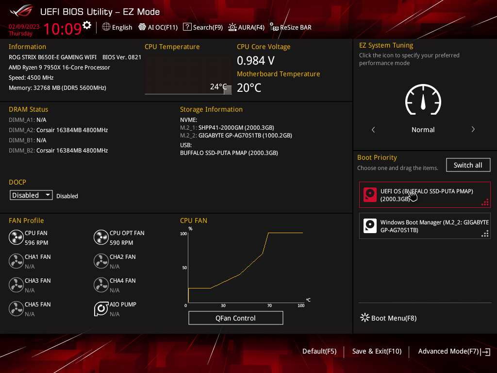
To install the operating system on the new computer, one should insert the USB drive containing the OS installer. Afterward, the computer should be powered on, which will lead to the booting into the OS installer. If the installation drive is not accessible, the user may need to access the BIOS and confirm that the USB drive is recognized as a boot device and is listed before any internal drives in the boot order.
Once the operating system has been successfully installed, upon the initial internet connection, Windows 10 and Windows 11 generally perform well in terms of acquiring device drivers. Nevertheless, it is advisable for users to visit the manufacturers’ product pages for their hardware components to ensure they have the latest updates or to acquire them as necessary.
Finally, when their operating system and drivers are all updated, it becomes time for the user to commence using their self-built PC. They can proceed to install games, stream movies, edit photos or videos, or engage in Discord conversations — engaging in their preferred activities with their PC. Furthermore, it’s important to bear in mind that whenever they desire to enhance their PC with additional features or boost its performance, they have the option to upgrade.
![The Best, High-Performance Solid State Drives (SSD) [2025]](https://pc-build.help/wp-content/uploads/2023/07/best-ssd-768x512.jpg)
![The Best High-Performance External SSDs [2025]](https://pc-build.help/wp-content/uploads/2023/08/best-external-ssd-768x512.jpg)
![The Best High-Performance Budget Graphics Card (GPU) [2024]](https://pc-build.help/wp-content/uploads/2023/08/best-graphics-cards-768x512.jpg)